Quarto Game with Roll-Up Board
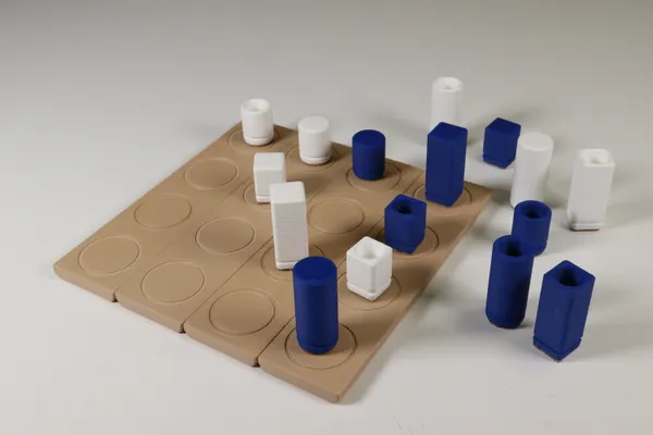
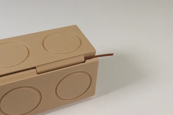
Quarto is a board game that can be learned in minutes yet still has plenty of scope for interesting play. This 3d printed version includes a board that rolls up into a box for storing the pieces. Learn more about Quarto here.
Important Notice
Quarto is published and copyrighted by Gigamic. I encourage you to support them if you just want to play Quarto.
This article discusses only the physical design for a folding game board and game pieces. That design is released under an open-source license. The license does not imply or confer ownership of the copyright on Quarto!
Printing
I printed everything in PLA using 3 perimeters, 15% infill, and no support material. The mesh files have all been exported in the proper orientation for printing. Print two copies of the piece set file; each in a separate color. You’ll also need two copies of the end-flap file. Just one copy of each remaining file.
Adding Weight to the Pieces
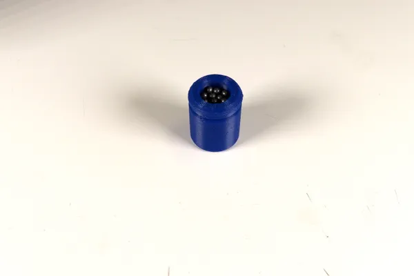
The pieces are designed with a hollow cavity at the bottom to accommodate some added weight. I used lead pellets harvested from an old diving weight.
The weight probably makes the pieces more resistant to tipping over, but mainly I think it just makes the pieces feel better in your hand! It’s optional of course. I’ve included a solid version of the mesh file if you’d rather skip it.
Finishing the Bottom of the Pieces
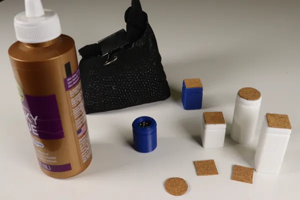
This step is also optional, but I think gives the pieces a very finished look. It also covers up the weights. You can use felt, cork or anything similar. I had some some thin 1mm cork sheet leftover from an old project. I think it originally came from a local craft store.
Stencil and Cutting Guide
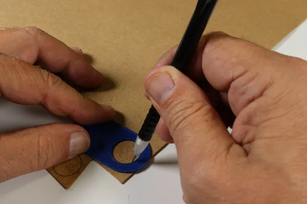
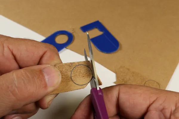
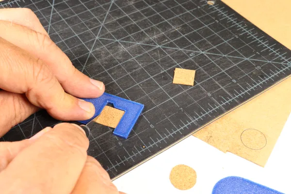
I made a stencil for marking the round cork pieces, then cut them out with small scissors. The square pieces were more easily cut by first making a strip the correct width with a straightedge. Then, I used the illustrated tool to cut them all the same size.
These guides are certainly overkill just for 16 pieces of cork. I included them mostly to illustrate how a simple 3d-printed fixture can help with repeated operations. They’re so small they print in just a few minutes.
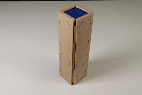
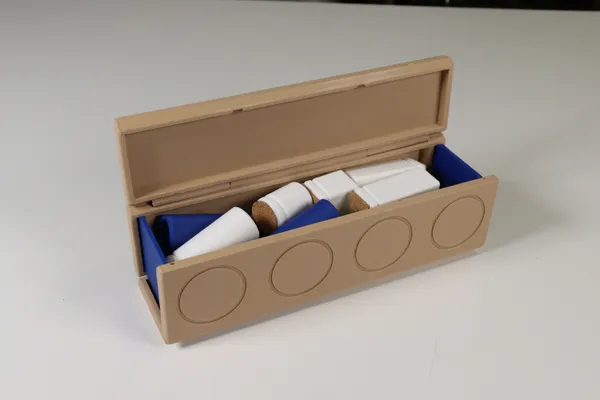
The Roll-Up Game Board
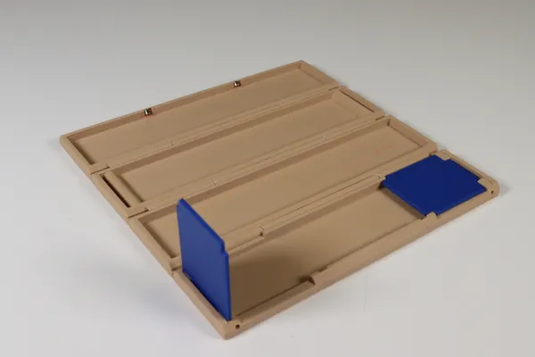
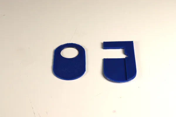
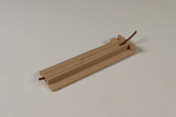
The board is made in four hinged sections as shown. Two end plates fold up underneath the first section when the board is unrolled for use. They fit into a slot in the opposite section when the board is rolled up.
Four small magnets keep the board closed. You’ll need a dab of glue to hold each magnet in place. Be sure to get the polarity right when gluing them in!
I used magnets I had on hand. They are imperial sizes: 3/16" diameter by 1/8" thick and are N42M grade. I used four of them after discovering that two didn’t reliably hold the box closed. They’re mounted diagonally in the edge of the board so that their faces are parallel when the board is folded shut.
The hinge pins are short lengths of 1.75mm filament simply slid into place. I adjusted my clearance values for a nice friction fit, but if necessary, you may add a tiny amount of glue just near one end. Take care not to get any on the rotating part of the hinge. So far, I’m finding these plastic hinge pins are holding up very well. You could probably substitute steel music wire or some other type of metal pin.
Print the Sample Hinge First
I have modeled a small hinge test piece, which I recommend you print and test before printing the entire board. The filament should be a snug fit in the outer sections, but should be a nice running fit in the central section.
This test was made by cutting two of the board sections down to a smaller size for faster printing. When I was finished testing clearance, I simply suppressed this intersect feature (near the end of the timeline in the Fusion 360 document), and exported the parts as usual.
I found that it is important to keep the length of the test hinge the same as the final hinge. It turns out the friction can be substantially higher as the hinge gets longer.
If either hole size needs adjustment, edit the Fusion 360 file; alter the fit_clr and/or run_clr parameters; then re-export and re-test. You can repeat this test as many times as your patience allows. For a detailed explanation of how I use these two parameters, see the Clearance and Tolerance section of my last post.
Also note that if you’ve never calibrated your printer before, I recommend you spend a bit of time on that first. The procedure outlined at Teaching Tech is an excellent place to start.
And, of course, remember that the fit_clr joints can always be helped with a bit of glue if they’re too loose. And any joint could be opened up with an appropriate drill bit if you happen to have one long enough. That’s not cheating!
The mesh and CAD model files are available at Printables.com or Github.