South-pointing Chariot
The South-pointing Chariot was an ancient Chinese invention, supposedly used for navigation. Read all about it at Wikipedia.
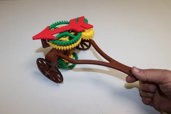
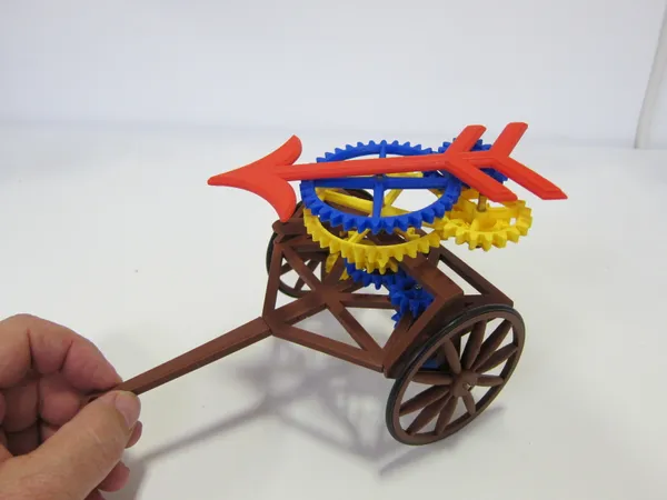
No matter which way the chariot turns, its pointer continues to point in the same direction. This one must be manually pointed South before starting (unless you’d prefer some other direction).
My chariot would not work well for navigation, due to wheel-slippage and inevitable imperfections in manufacture, but it’s an interesting toy to play with, and that’s reason enough to make one!
How Does it Work?
Like most others, this one uses differential gearing. A differential gear train turns its output at the average speed of two inputs.[1] If the inputs turn the same speed but in opposite directions, the output will be stationary.
Each wheel is geared to one of the inputs, with the pointer fastened to the output. While moving in a straight line, both wheels turn the at the same rate, and the pointer remains stationary.
But, as the chariot rounds a turn, the outer wheel will turn faster than the inner, causing a change in the differential’s output. The pointer turns!
Proper operation also depends on the ratio of the wheel diameter to the distance between the wheels, or track. If we make this the same, the wheels may be geared to the differential in a 1:1 ratio.
My design uses a slightly wider wheel:track ratio of 3:5 (84mm:140mm), simply for esthetic reasons. To counteract this, the bevel gears are also 3:5.
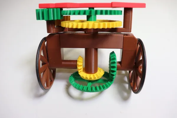
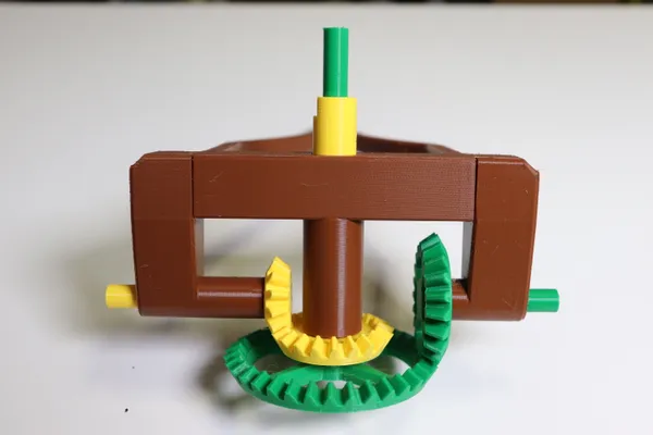
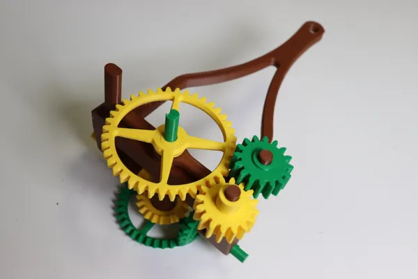
Note that while one set of bevel gears is larger than the other, each set has a 3:5 ratio. The larger set (green in my rendition), has a tooth count of 21:35 while the smaller (yellow) set is 12:20. One side is made larger, simply so that we can make the vertical shafts concentric.
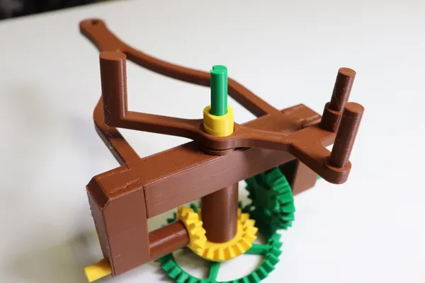
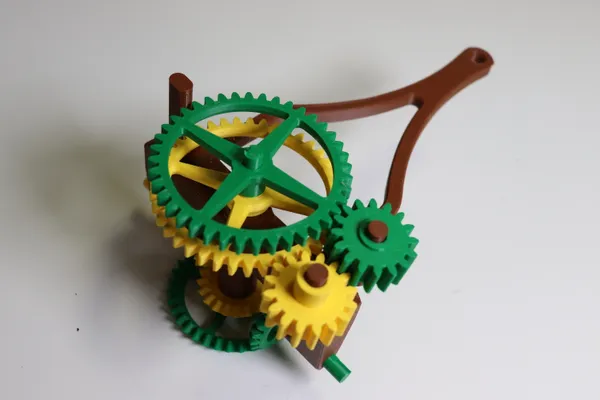
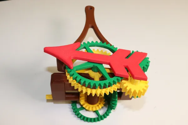
For variety, I chose a spur gear differential, situated on top of the carriage. It has large spur gears to highlight their opposing rotation, and incorporates the pointer into the differential’s cage. I also choose a color scheme that I think helps understand the device’s operation.
In addition to PLA, you’ll need two O-rings for tires[2], and possibly some glue. In my case, I only needed glue to fix the wheels on their axles; everything else was a press-fit.
Printing
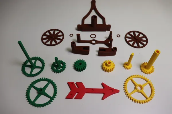
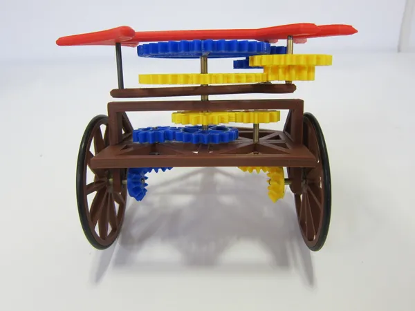
I did not rotate the STL files when exporting. When printing, they should be oriented as in the above picture. No support material should be necessary. I’ve used ordinary PLA for everything, with 3 perimeters, and 15% infill.
A few of the parts have tall, narrow shafts printed vertically. My printer had no difficulty printing these parts, though the slicer did slow the print down due to the small surface area. I recommend printing the these parts individually to minimize printer vibration.
These shafts are stronger than I thought they’d be, but do require reasonable care during assembly. Once the chariot is together, they’re much less vulnerable.
Assembly
Before assembly, clean off any strings or blobs, and test-fit the rotating parts to make sure they all turn freely on their shafts.
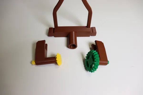
Be sure to put the side bevel gears into their chassis pieces before assembling the chassis, you won’t be able to fit them in later. The side pieces simply slide onto the main chassis body as illustrated. Mine was a snug fit requiring no glue, but add a dab if yours needs it. I use thick cyanoacrylate glue for PLA.
Now add the remaining parts in the sequence illustrated above. Don’t forget the spacer between the chassis and the bottom gear cage piece. Glue the spur gears to their shafts if necessary, but do not get any glue on the turning portion of the shafts.
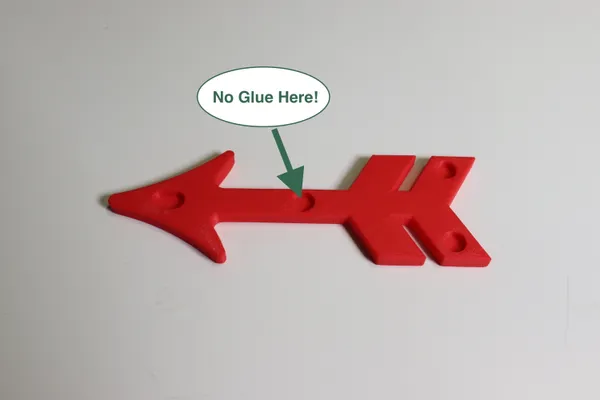
The next part to add is the arrow, which also forms the top of the differential cage. Again, glue if necessary, but do not apply any glue to the center hole! The vertical shaft must run freely in this hole.
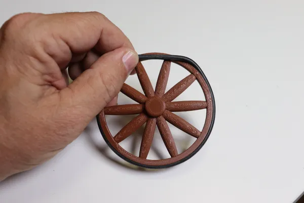
The O-rings tires are simply snapped into place. You should not need any glue. They are: 2-7/8"ID x 3-1/8"OD x 1/8" cross-section (before stretching onto the wheel). If you can’t find them locally, I found an online source here.
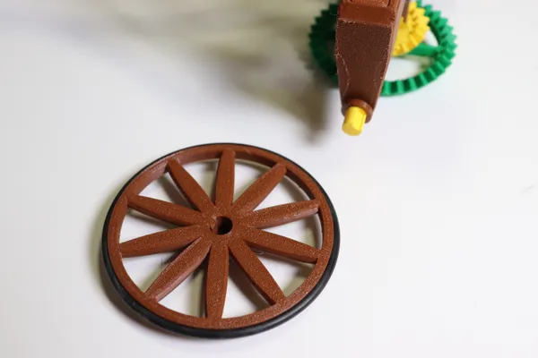
Finally, add the wheel spacers and wheels, again being careful to keep glue off the moving part of the shafts.
Enjoy!
History and Design Notes
(You don’t need to read the following to make a chariot.)
My First Attempt
Here’s my first version of this device, made way back in 2016. I wrote a brief post back then on the Ace Makerspace blog.
The design worked well, but it was tricky to assemble. I used steel pins and brass tubing for the axles and nested shafts. This makes for a long-lasting bearing, but the materials and techniques are not familiar to everyone. Also, the printed parts had to be glued to the shafts, which was very tricky to do without getting glue in the rotating parts and ruining the whole job.
I balked at publishing it out of fear that nobody else would have the patience to build one besides me. Certainly those who failed in the attempt would hate me forever!
The new version is simpler, more robust, and just as much fun!
Printed Shafts and Bearings
This is the first time I’ve made anything that uses simple plastic-on-plastic bearing surfaces. I was surprised at how well this works.
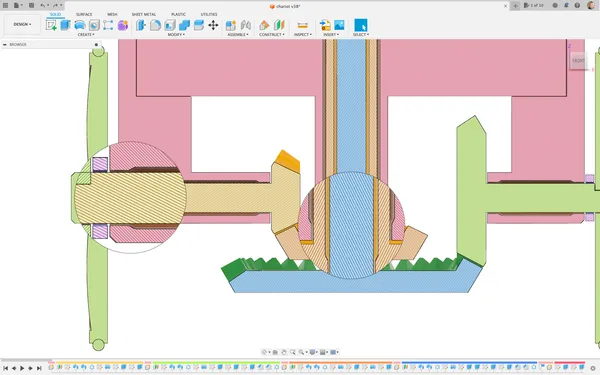
I did use a design trick to reduce friction. The long holes for the axles and nested shafts are shaped as shown above, with just a small bearing surface at each end. The central portion of the hole does not contact the shaft.
Clearance and Tolerance
I’ve helped a lot of folks get started with design for 3D printing, and the following points are often missed.
When designing mating parts from rigid materials we must always allow for a bit of clearance in order for the parts to fit together. There must be a gap at the interface between the parts. Smaller gaps will give a more precise mechanism, but may be more difficult to manufacture and assemble. The gap may not be zero. (Unless the material can be stretched or compressed).
We must also expect some dimensional variation of the parts. This is true regardless of the manufacturing method and machinery, from the most elaborate CNC equipment down to the simplest 3D printers. There is no such thing as perfection.
The design must be tolerant of these variations. If the product will only tolerate small variations, we’ll need expensive manufacturing equipment. Sometimes that’s unavoidable. But, in most cases, we try to accommodate the all the variation we can reasonably expect.
This is Mechanical Engineering 101, but a lot of beginners seem to assume that computerized manufacturing will be perfect, rendering these messy details unnecessary.
No matter how accurate your machine is, you should never expect an 8mm shaft to fit in an 8mm hole. Get used to working with clearance values.
Clearance and Tolerance in 3D Printing
Unfortunately 3D printed parts can vary enormously, due to a lot of variables: inconsistent filament, the machine’s mechanical design, and the lengths to which the operator went while tuning the machine and print settings.
If I’m designing for someone else’s printer, I can’t predict the variation, so I accommodate it. In my designs I now incorporate at least the following two parametric values that can be tuned to suit the machine or material. They provide desired clearance, and are set appropriately for my machine. Since they’re implemented as parameters in the design, you can change them to suit your own machine.
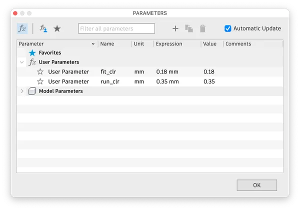
I call these variables ‘run_clr’ and ‘fit_clr’—my shorthand for running clearance and tight fit clearance respectively. I define these as:
- run_clr
- The additional space left between parts that must move with respect to each other after assembly. Axles turning in holes are an example.
- fit_clr
- The additional space left between parts that should be a tight fit, and should not move after assembly. If very well chosen, such joints may be a friction fit, and not require any adhesive or fasteners.
The values that worked for me in this design are: run_clr == .35mm, and fit_clr == .18mm.
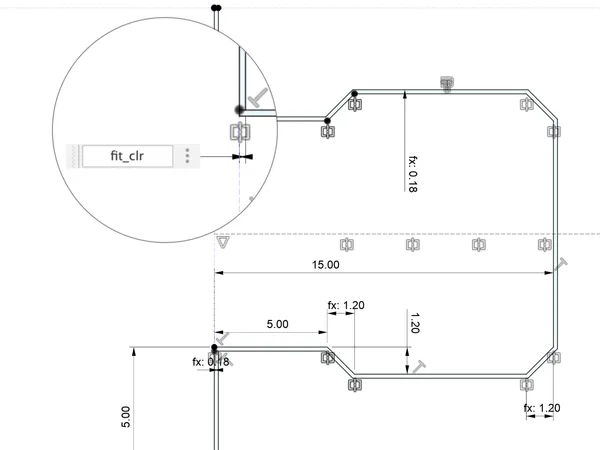
When creating complex intersections I can simply offset the outline all-around by the desired clearance value. Or sometimes I design the part as one piece, then perform a narrow cut to divide the part into separate bodies, using the clearance variable as the width of the cut. This is the technique I used for the chassis joint shown above.
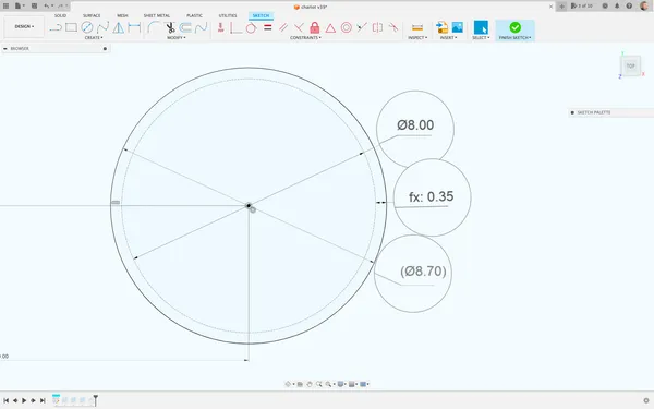
Note that this can be a bit confusing for circular holes. Since I apply the clearance value to entire perimeter, the hole’s diameter is increased by twice the clearance value, i.e.: an 8mm shaft requires an 8.7mm hole for a running fit. If you find this too confusing, you might want to make another variable just for circular holes.
I have found that these two variables are a good starting point for any design, but of course there’s much more to it: very small holes seem to require more clearance than larger ones, and horizontally arranged holes behave differently than vertically arranged holes. Also, slicers are improving all the time, and may affect your design-habits. Be prepared to learn, and make your designs flexible.
Download the Design Files and Experiment!
The STL and CAD source files are available on Printables.com and my Github page.
If you use Fusion 360, the clearance values I mention here should be available after importing the F3D file. If you use a different CAD program, look into its parametric features to see if you can accomplish the variable clearance technique I’ve described here.
Good luck with your own 3D designs!